Hammer (Beam) Time
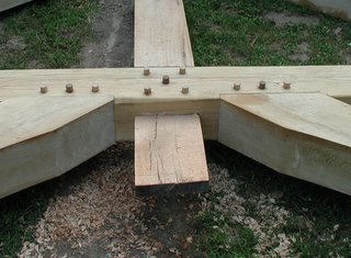
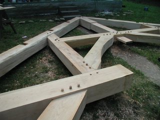 The simplest and most effective way to span our 24 foot wide great room would probably have been using a king-post truss... even though it would have required cutting a 24 foot rafter tie on my 20 foot saw mill. However, hundreds of years ago, the English came up with a much more spectacular (convoluted?!) way of spanning large rooms (in churches, great halls, and castles), using short timbers. These trusses are know as hammer beam trusses. All of the glossy timberframe picture books include at least one picture of a timberframe with a hammer beam. So it should come as no great surprise that my wife required a hammer beam in our house.
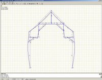 Although you can find pictures of them everywhere, precious little useful (buildable) information can be found written about hammer beams in the timberframe books. (exceptions noted in my book review) I downloaded at least 40 pictures of timberframe trusses from various web sites on the internet and studied them. Then I downloaded a shareware structural analysis program from the internet, and plugged in some configurations and noted how the forces were distributed within the structure, and which members were being subjected to the most stress. Based on this (and many other constraints too numerous to list right now), I came up with a hammer beam design of my own that I felt confident would work. Given that all of the trees used to build our house were felled as the result of a catastrophic ice storm, the likes of which no living person had ever seen before in our area, I decided to use snow loads typical for Colorado or Maine in my calculations.
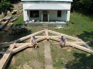 In this picture, you see Scott Stevens (instructor of Grand Oaks timber framing) and myself sitting on a nearly completed hammer beam truss for my house. We're sitting on the ends of the actual hammer beams themselves. On three seperate occasions Scott has travelled to our farm in Kentucky and helped with the joinery for our house. We built this hammer beam truss on his second trip to our farm. I thought this hammer beam piece was serious enough to warrant the involvement of at least one seasoned timber framer, and Scott was as big help.
On a timberframing-difficulty-scale of 1 to 10, with 5 being the king post truss and 9 being hip roofs, I'd consider hammer beams an 8. In other words, after I got into the nitty-gritty of timberframing, to my surprise, I found hip roofs to be harder than hammer beams. (I reserve 10 for cruck frames or other roof structures that I've not yet tried to build).
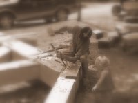 A few more details about this interpretation of the hammer beam truss: (1) I have yet to saw the curves in the lower braces, and still must carve the ends of the hammer beams and the king post - but these are aesthetic, not structural issues. (2) the truss is assymetric, i.e. the left side has a 3 foot overhang incorporated into it (a concession to passive solar design), whereas the right side will join the rest of the house and can therefore use a smaller post. (3) all of the joints are housed. (4) both posts are 20 feet tall, and since these pictures they have been cut into a "gunstock" pattern. (5) the big post that my youngest daughter is helping me trim in the B&W picture is a 12x16. (6) the wood used in this assembly is white oak, red oak, and ash.