Thursday, September 28, 2006

Head scratching at the top of the tower

The tower top has really given me some recent moments of head scratching and hair pulling...

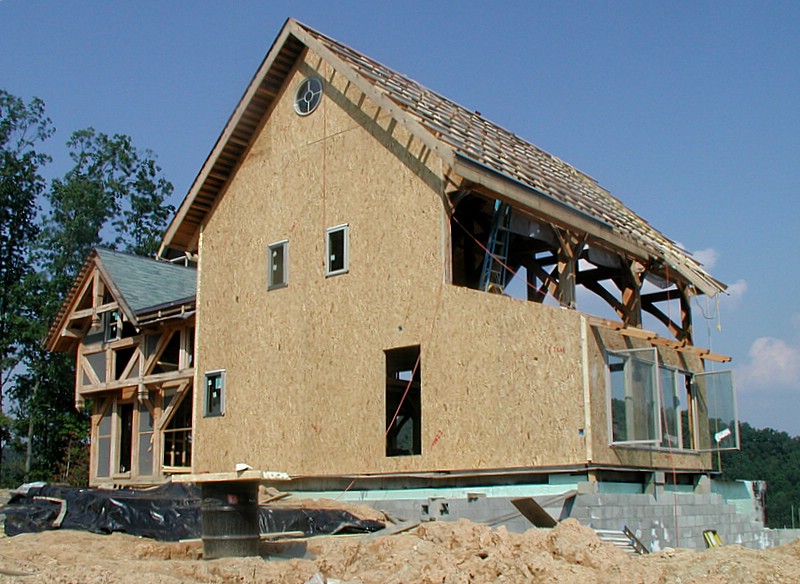
First a little tower trivia. Ever notice that a lot of towers have a little skirt at the base of the tower roof? I always thought that flair in the roof was just for style, but in the course of building this house, I've realized why tower roofs have this feature. Most tower roofs have a very steep pitch, and the rafters obviously have to hit the top plate of the tower wall. To get a proper roof overhang for most (non-steep) roofs, you simply run the rafters past the top of the outside wall. For a moderately steep roof (45 degrees or 12:12 pitch), 18" of overhang will lower your eaves by 18". But if you try to do this with a very steep roof, by the time you've achieved say 18" of overhang, you've lowered your eaves by at least 3 feet and covered the windows of the top floor of your tower. So that's why (I think) most towers roofs change pitch (flatten out) just before the eaves!

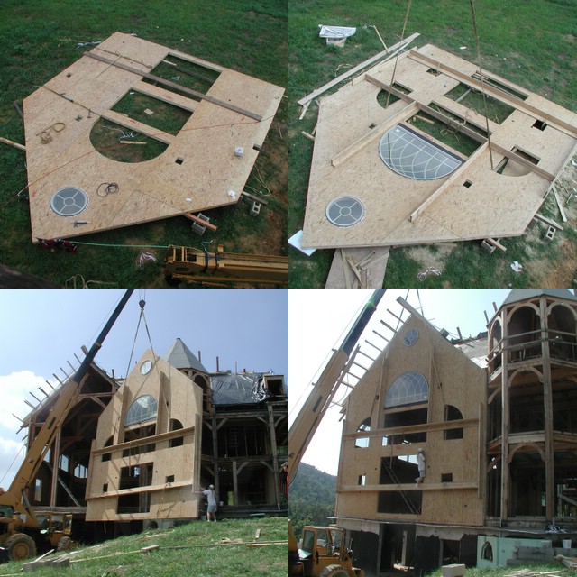
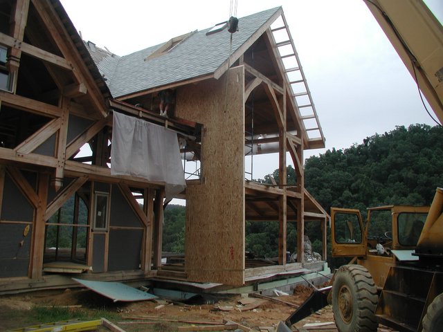
Implementing this flair has been a challenge. Every night this week, I've gone to bed thinking about it and woke up the next morning thinking about it (what, me worry?) . But now I think we have a solution that will work. My timberframing doesn't have this flair-out built into it, so we've had to build it in an ad-hoc fashion on top of the timberframing, using 2x10's and lots of radiussed and bevel cuts. The space between this 2x framing will hold my insulation (just like the rest of the roof). The picture at the top of this text shows the tower top with 8 of the flaired hip rafters in place. The picture to the right shows the base of one of these flaired rafters.

At first, I was going to abruptly change the pitch of the tower roof from 60 degrees to 45 degrees, 2 feet from the eaves (i.e. bottom edge) of the tower roof. But then I realized that would require a band of copper flashing to cover the nails in the slate, where the roof pitch transition occurred. I didn't like the thought of messing with all of this flashing, nor did I think it would add any aesthetic appeal to the roof. So, back to the fairy tale pictures of tower tops... On old castles and such, they often inserted a radius between the change in pitches, so the slate could lay relatively flat during the transition between roof pitches, and no flashing was needed. That's what I decided to do. But this caused another issue...

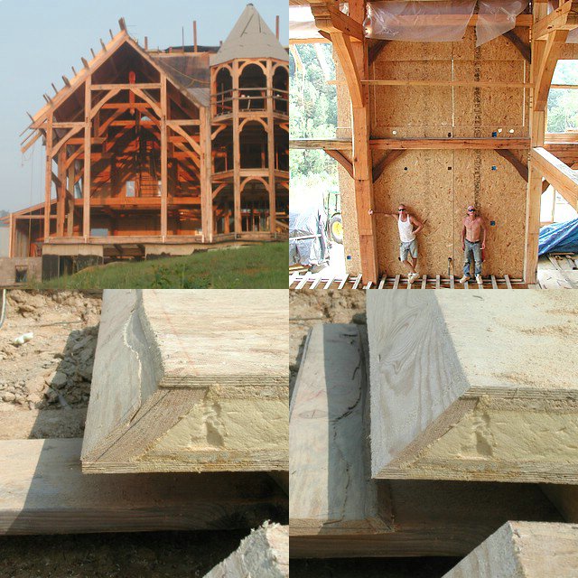
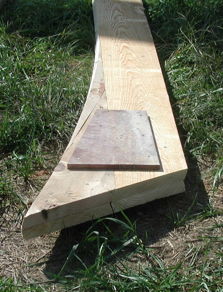
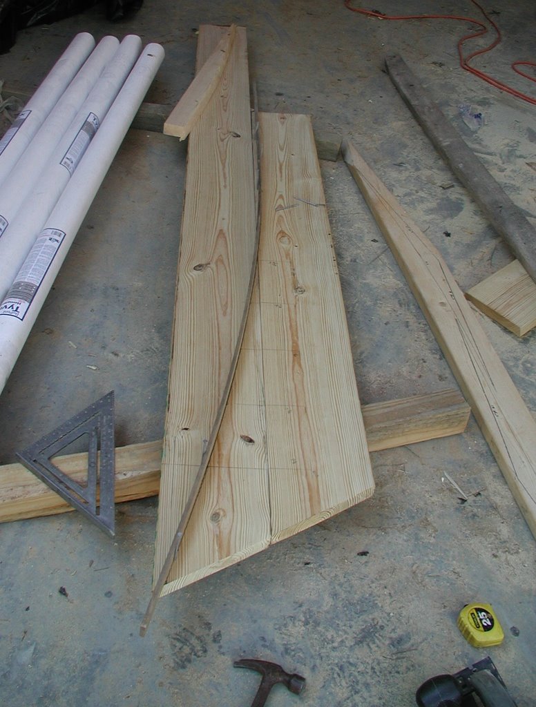
The hip rafters are 6 feet apart at the base of the tower roof. Spanning this distance with 1x4 sheeting and supporting it mid span with a 2x6 laid flat on rigid foam insulation (as I did elsewhere on the house) was not going to work here. The reason was that the foam insulation would not have the same radius as the hip rafters. So, I decided to insert a rafter, midspan of the hip rafters. To figure out the shape of this midspan rafter, my brother-in-law and I pulled a string between two hip rafters, recorded the numbers at 8" intervals, and then plotted these points on a 2x10. I used a thin strip of wood (see picture at left) to form a gentle curve that would "connect the dots," and traced this line on to what would become the midspan rafters. Unlike the hip rafters, these rafters do not require a bevel cut on the tops and bottoms(thank goodness!). I saved the first one as a pattern, and test fitted the second one. Rather than span 3 feet with my own 1x4 nailers, I'm going to use store bought (southern yellow pine) 2x4's. I think it will work.

Presently, I think the tower looks "cartoonishly top heavy." I expect the proportions of the tower top to the tower walls to improve substantially when I face the tower walls with stone quarried from our farm. The stone will grow the walls outward by 8" (6" stone + 2" air gap).

Friday, September 22, 2006

Tower SIPs are on

We finished the tower SIPs, and the house is starting to take form. I took this picture from the other side of a pond that I built before I even started on the house. (I wanted to know whether it would hold water before I placed the house smack dab behind it on the hill!) My friend helped me build this pond - not counting the spillway, it took us 3 days - he was on the bulldozer and I was on the backhoe. I have some pictures of the pond construction process that I'll blog when I get a little more caught up on the house. Rain is forecast for today, so this morning, we'll try and tarp what needs to stay dry. Posted by Picasa

Saturday, September 16, 2006

Building SIP walls on the ground

The SIP panels that I ordered are kind of like a giant puzzle. Because they are joined by tongue-and-groove seams, there is occasionally a "preordained" sequence that must be followed in order to assemble the panels. And sometimes, this means trying to fit small panels on top of large panels 30+ feet in the air. Getting everything square and aligned with the timber frame and then inserting windows into the walls (at this elevation) can be quite difficult. Searching for a simpler (and safer) way to accomplish this, I decided to assemble ten of the panels together on the ground and fly them together all at once. In fact, we prehung the two most difficult windows in the assembly before flying it on to the timber frame. The photo-collage shows the sequence of events.

To keep things from bowing when the crane lifted the whole shebang, we made "walers" and "stiffbacks" out of 2x10s and secured them to the panels, . We first did a test lift with only the small window in place. After observing that the assembled bowed very little during the test lift, I decided to place the large semi-circular window into the assebmly as well. I would guess the semicircular window (8 feet by 5 feet) weighs over 250 lbs (it is difficult for 3 men to handle on solid ground), and putting it into place after the wall was lifted would have been no fun. To lessen the risk of cracking the large window during the lift, we only partially drove the nails that hold the window's nailing fin to the wall. This gave a little bit of play between the very rigid glass and the semi-rigid panels. It was a risk-vs-reward decision and the risk paid off for us.

As soon as we had the giant wall in place next to the timberframe, we quickly drove several of the panel screws into the frame, and then removed the crane rigging. This picture shows this interior wall of the timberframe and how its braces align with the windows. My wife and I morphed this design from several pictures we saw in magazines. We spent hours iterating between commercial window offerings and possible brace locations and radii. We are really pleased with how it turned out.

By the way, my wife selected all of the windows for our house, and ended up ordering about 70% Jeld-Wen brand windows and 30% Andersen brand windows. The styles are very similar, so if you pay attention, you can use the two brands together in the same room. The decision to use Jeld-Wen windows was largely price-driven, and Andersen windows were used only where Jeld-Wen did not have a viable offering for what we needed. With that said, I can tell you that the Jeld Wen windows appear to us to be of a much higher quality than the Andersen windows, even though the Jeld Wen windows are about 2/3's of the price! One reason the Jeld Wen windows seem so much sturdier could be that they have an aluminum exterior cladding whereas the Andersen windows have vinyl exterior cladding. The aluminum makes the wooden windows stronger, whereas the vinyl cladding more-or-less just protects the wooden windows. Of course the vinyl won't conduct heat as readily as the aluminum, but when you handle and install the aluminum clad windows, they feel like they're in a league above the vinyl clad windows. I should also mention that the aluminum nailing fin on the Jeld Wen windows lays a lot flatter on the exterior wall after being nailed. I will admit that I was a skeptic when my wife suggested buying "Jeld Wen" windows, whose name I couldn't even pronounce, but now I must concede that she really did her research.

Monday, September 11, 2006

Sunroom SIPs are Complete

Today we finished applying the SIPs to the south facing sunroom (breakfast area), installed a french door, tarped the sunroof roof, and put down more standing seam metal on the upper south roof. All of today's progress is summarized by this single photograph. Everywhere it is feasible, we are trying to immediately follow the panels with roofing and windows - in order to avoid exposing the edges of the panels to very much sun or rain (foam insulation doesn't like UV and we all know that OSB edges don't like rain). We have been very fortunate so far with the weather, but rain is forecast for tomorrow. Posted by Picasa

Saturday, September 09, 2006

SIPping along the south wall

Short entry this (Saturday) evening...

Upper left picture is the frame this morning at 7:45 am. With walls come shadows and I thought they looked neat so I snapped this picture.

Upper right picture is today's crew at beer thirty (consisting of one inlaw and one outlaw). Why does this picture look like a police line up? :)

Lower left picture is a "factory cut" SIP edge. I could have lived with the sloppiness, but the dang panel was too tall. This stems (mainly) from the fact that the SIP company dimensions the panels according to the inside edge of the inside piece of OSB, but then makes their bevel cut from the outside edge of the inside OSB. In other words, they don't start their bevel cut at the edge of the SIP. Result: if your OSB is 7/16" thick and your pitch is 12:12 (45 degrees) then your panels are automatically 7/16" taller than what you specified. Wish I had known this before ordering my panels. If you buy precut SIPs, make sure you know how your panel supplier will translate the drawings into real panels. Also try to get a feel for their tolerances, and shrink your dimensions by at least their tolerances.

Lower right picture is after we recut this panel edge with a 16" Makita beam saw. Looks like we'll have to cut nearly all of our top panel edges. Wouldn't be so bad, except for the fact that the top plates have staples (and sometimes #8 nails), which means that I've already trashed a $99 saw blade cutting these panels. Even though most of the top bevel cuts are sloppy (or plain wrong in two cases so far), to say something positive about the panels I should mention that all of the rough window openings, electrical boxes, and conduit seem to be spot on, and I'm glad not to have to do that work later.

More SIPs go on

As we get underway with the SIP installation, we are moving up the learning curve and things are going a little easier and a little faster. For instance, we've decided to install windows as we go, while the crane is there in position to help us. Also we've found that it is advisable to check the width of the SIP tongues against the width of the SIP grooves before standing the jumbo (24') panels and trying to "slide/ratchet strap/pry" them together. I had always heard that polyurethane panels had looser tolerances than EPS panels due to the nature of their manufacturing processes. The polyurethane foam is injected between the OSB and allowed to cure in place whereas EPS foam slabs are premade and glued to the OSB. I committed to polyurethane panels (they insulate better and involve less waste at window openings) and never thought to care whether my walls were 1/8" thick or thin here or there, but now that we're trying to fit tongues-in-grooves, I'm realizing that I do care... at least when they don't fit! Our trick is to plane off 1/16" when the tongue is 1/8" too big, thereby converting an "interference fit" back to a proper "press fit". Before I leave this picture, I should point out that this is the west wall of our house, and therefore intentionally devoid of any large windows. The afternoon sun can get brutally hot and we didn't want to uncontrollably heat the house in the summer.

Another trick that we tried (and it worked!) yesterday was to assemble 4 smaller panels together on the ground and fly them as a single unit. (see lower right picture in the photo-collage.) Actually, we didn't intend to do this to speed things up... it was the only way we could see to install these particular panels, since three of them are notched for rafter tails and therefore can't be slid sideways (in order to mate the tongues and grooves) once they are placed on the timberframe.

The top two pictures of the photo-collage reveal the inside of the house. The rightmost of these two pictures shows the kitchen wall, where the panel manufacturer has included electrical recepticles (and embedded conduit) for appliances. The leftmost of these two pictures shows my welder sitting in the sunroom. You can also make out the concrete forms for our fireplace slab - as yet to be poured. (look for the green rebar). Finally, in the lower left photo, you can see where panel-progress was held up until I finished welding some of the stainless-steel termite flashing - in a particularly difficult intersection of walls and posts. Yes, that's charcoal you see on the bottom of my post - I caught the post on fire a few times while welding. Thankfully, big chunks of wood really don't want to keep burning.

We are now working 7 days a week in a race to get these panels on and at least a temporary roof on the house before weather turns bad this fall.

Friday, September 08, 2006

Butt holes contributing to a self sufficient home


One of our goals with this house from the beginning has been to build a self-sufficient home. At the outset, I designed the largest continuous wall and roof plane of the house to face solar south. The south wall will have lots of windows for passive solar heat gain and the south roof will be covered in solar electric panels. Solar electricity is currently very expensive - it will take approximately 30 years for our solar panels to produce enough cumulative electricity to justify their initial purchase price (if energy prices remain constant). Given the high price of solar electricity (relative to the coal and gas fired electricity I could buy from the grid), it makes little sense to operate appliances like ovens, stoves, and clothes dryers with solar electricty. In fact, it's almost a prerequisite to operate these heat generating appliances from natural gas or propane if you're going to live off the grid and generate your own electricity. But, aye, there's the rub. Isn't it self-defeating to build an off-grid house that must also run on propane or natural gas? It seems to me like trading one devil for another. Unless...

One renewable source of natural gas that has intrigued me, ever since I started raising cattle on this farm, is the conversion of cow manure to methane. I've read about it on the internet and in some 1970's books on self-sufficient houses, but I was never sure how difficult it would be to do it myself. (just like timber framing!) The best way to learn is to try, so a few weeks ago I plumbed an old 55 gallon oil barrel, poured out some salt and minerals on the ground, called for my cattle to join me in the back yard, and waited for them to poop everywhere. I followed them around with a shovel and a 5 gallon bucket for about an hour. I filled the 55 gal drum with a slurry of cow poop and water and waited for several days. Would it work? Would the traces of old diesel fuel in the drum or the chlorine in the tap water prevent bacterial methane production?

The 55 gal drum is of course a scaled down prototype of what I would use for my house gas generation. I think I will need about a 1,000 gallon tank (already bought it at a farm auction for $50) and the manure of 7 confined cattle. My cattle are free-ranging, but I have 40 head, and I think that if I place a concrete pad in a central location where my cattle come to get their water and minerals, I can capture the equivalent manure of 7 confined cattle in this loafing area. I'd use a hose to wash the pad off occasionally (when it wasn't raining frequently enough) into a drain that would gravity feed to the methane digester. That's the big plan... now back to the small plan...

Within a few days, I had bubbles coming out the water trap of my methane digester. I didn't get too excited because I surmised these bubbles would be CO2 - the result of "aerobic" microbes. I hadn't purged the drum of oxygen, so based on what I've read, it is normal to expect aerobic digestion to occur for several days as a precursor to anaerobic digestion. Each day, there were more bubbles... venting to the atmosphere, because I had resolved not to waste my time with building the gas-storage stage of the methane digester until it actually produced methane gas. Seemed like a good idea at the time - but I soon found that my logic was flawed. You see, at night, the temperature (and therefore pressure) of the digester dropped low enough that it sucked the feed pipe of my digester empty, allowing oxygen to enter the digester every night. I would need a gas storage aparatus... if for no other reason than to accomodate the 24 hour rhythmic pressure differences in the digester. But what to use?

I told my wife... I need one of those mylar balloons. My 2 year old daughter overheard me. She had watched the older kids help me build and fill the digester, but now she saw her chance to contribute. Quickly she volunteered... "I have berry cake balloon. You can use it." She went in the house and came out with a balloon that still held helium. I tried to explain the irreversible consequences of her intended donation, and she nodded her head that it would be fine, but I was certain she couldn't fathom it. The moral dilema was gut wrenching for me... would I actually empty my daughter's perfectly bouyant helium-filled Strawberry Shortcake balloon and fill it with artificial cow flatulence? Of course I would! I rationalized that methane (CH4) is lighter than air, and although the helium release would be permanent, her balloon might actually float again with swamp gas in it.

I painted the drum black (except for the wonderfully ironic Quaker State logo on the side), to help with solar heat absorption. (Methane generation works best at some temperature range that I think is close to internal body temperature.) The balloon soon filled and then the overflow realease mechanism (a msaon jar with water) vented bubbles into the atmosphere. At night, the balloon got saggy, but allowed no new oxygen to enter the digester. Surely this could be working now! But I got busy with the house - really busy. I watched the balloon inflate and bubbles release every day... and weeks passed. Was I really generating methane? How much? When would the first charge of manure run out? I needed to conclude the experiment soon, before daily temperatures dropped too low for my uninsulated methane digester to be viable.

Finally, yesterday, I got up my courage to try and light some of the gas in the balloon. At first I couldn't really get anything to light. But I didn't have a proper aparatus for burning gas - I was simply trying to squeeze gas out of the balloon (through clear U-shaped hose with a water trap in the bottom for safety). Every time I got gas flowing out of the pipe, water would spurt out with it and extinguish my pilot light. The gas didn't seem explosive, so I dispensed with the water trap and started squeezing the gas out of the balloon straight on to a pilot flame. Eureaka. Although I couldn't develop a self-sustaining flame (because I lacked a proper burner), I could squeeze gas directly on to a flame (with the balloon under my arm and actuating it like bagpipe bellows) and get a much hotter, bigger, bluer flame than the pilot flame itself. My next step will be to find a proper burner/orfice and see if the gas is pure enough to provide a self-sustaining flame. In the mean time, I think my digester is making some Berry Sweet gas! [Kids, and litigious adults, please don't try this at home!]

Thursday, September 07, 2006

Sipifying

We've started applying the Structural Insulated Panels (SIPs) to our timber frame. Because we had to wait so long on the panels and our frame was exposed to the elements, I decided to start roofing the house many weeks ago. Typically, this is not the order in which things should occur. I knew that the roof overhang would make it difficult for us to apply the SIPs later, but I felt like I had no other choice. Now we are "paying the price" for putting things out of order. In the first picture, we've passed the crane cables through the roof in order to rig one of the panels for lifting into place. (lucky for us there's only a roof frame here.)


In the second picture, you can see the delicate balancing act we're having to play with the panels and crane rigging in order to not tear off the slate roof that's already on the house. Just after this picture was taken, we had to remove the crane rigging from the SIP and finish placing this SIP by hand. Fortunately, not all of our house has been roofed. After we get these difficult panels placed, things should go quicker where there is no roof overhang to interfere with the crane operation.

Materials have arrived!

Last week, our standing seam metal and Structural Insulated Panels (SIPs) both arrived!

The entire south roof of our house will eventually be covered in photovoltaic solar electric panels. It didn't make any sense to roof that portion of the house in slate and then cover it up with solar panels. Plus, I couldn't figure out an easy and leak-proof method of attaching the solar panels to a slate roof. I did however find some nifty extruded aluminum clamps from Unirac that allow you to attach solar panels to a standing seam roof without making any penetrations through the roof. So, I decided to roof the southern portion of our house with gray standing seam metal. A local supplier was able to order it for me and the metal was custom manufactured, cut to exact lengths, crated, and delivered in less than 2 weeks!

Procuring our SIPs was not nearly as easy. Over 5 months after we sent in our 50% deposit to Thermocore, they were finally able to manufacture our SIPs. I'll have a lot more to write about the SIPs later... In the mean time, here's a picture of nearly all of the walls for our house... on one truck!