As it turns out, the ground beneath our farm contains several even beds of fine grained sandstone (aka siltstone). In fact, sandstone was once quarried in our county (100 years ago) and sent all over the country (e.g. Chicago and New Orleans). Evidence of that the stone was once highly valued can still be found -- our stately courthouse is built of it (c.1939) , and abandoned quarries are still marked on the topo maps. Unfortunately, most of the knowledge of how to work this stone disappeared when the quarry workers passed away.
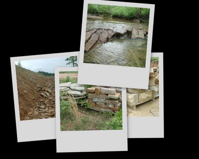
The stone is hard to ignore on our farm ... it pops out here and there on old eroded logging roads, and 12" waterfalls flow over the exposed beds in the creeks. Where the weather has liberated the stone completely from the ground, it usually comes out in nice rectangular chunks. It was slow going clearing the ground for our house site, because everytime I saw a rectangular rock, I had to jump off the dozer and put it in my "save" pile. Surely these "freestones" deserved a place in our house.
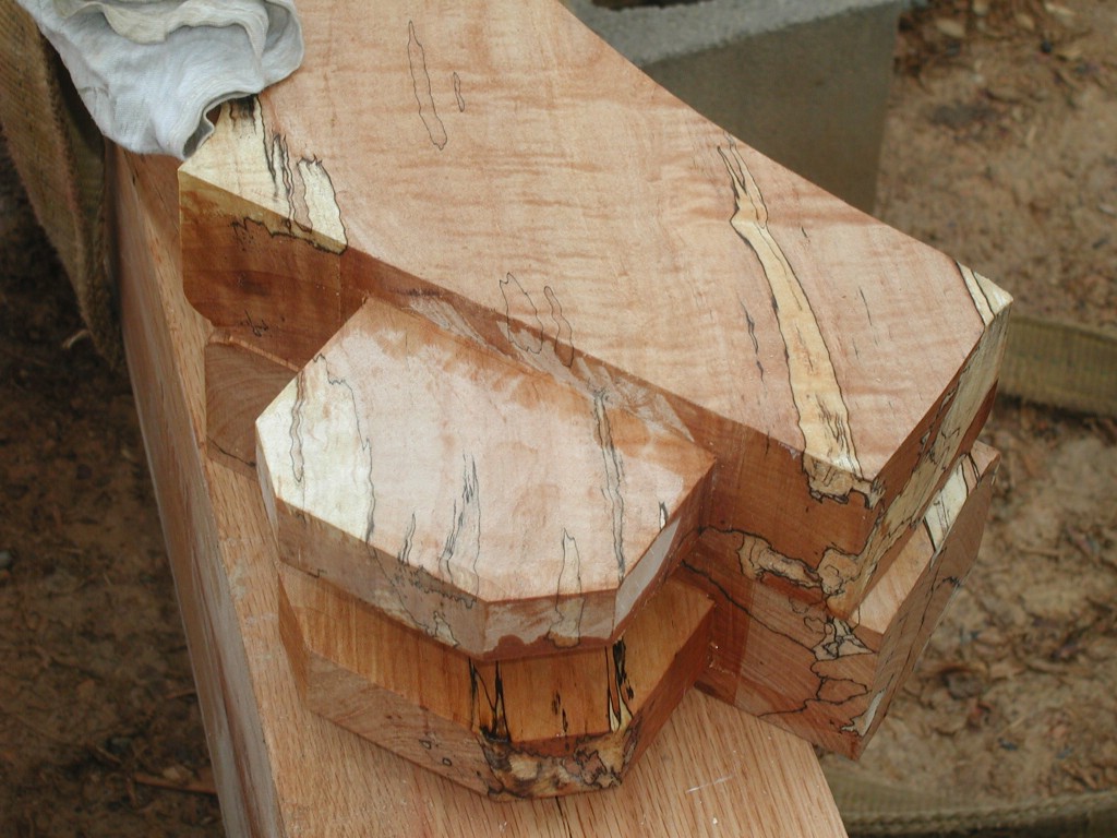
Building the road to our house site unearthed even more nearly-square stones, but it was clear that many more stones would be needed for our timberframe house. And a lot of these freestones would need "working." I showed my collection of stones to a Welsh stonemason and to Mr. G, my 7th grade science teacher (who, among other things, is the resident authority on local geology). When asked whether these particular stones were worthy of building a structure that would last hundreds of years, they both answered emphatically - "of course!"

I met the Welsh stonemason through a friend of a friend. He showed up for several days, splitting the rocks with chopsaw and chisel, and facing the resulting rectangles with a chisel and mallet. The look was nice, but my wife worried that they were almost too formal... "it'll make our house look like the courthouse," she said. I worked beside him for a few days, serving him lemonade, and listening to his windy stories about all the things he had done in life and all the things he could do. After making about 6 pallets of stone (and getting paid for the 6th) the stonemason failed to show up one day. In fact, that was over a year ago and I haven't seen him since. (I later heard that he had a nasty break-up with the friend's friend.) Fortunately for me, he left me with his hammer and chisel and a little bit of know how.
After he left, I made about one more pallet of stone in his "pitch faced" style. Man, it was rough work. I was starting to see why all of the quarries were abandoned in our county! Through out all of this, Mr. G. had been dropping by and telling me that you could split this stone easily with something like a log splitter. The stonemason had vehemently disagreed with this proposition... "Sounds like a typical American idea! hmmmph! Why, you'd have no idea of where the fracture would occur, if you didn't do it by hand, chisel, mallet, and use a keen eye." But the stonemason was now long gone, and I needed at least 40 more pallets of stone for my house.
For ships-and-giggles one day, I borrowed a hand operated log splitter and put a rock in it. Mr. G stopped by just in time to see me try this... pump, pump, pump... craaaaaaaaaack! A perfectly square split with nearly zero effort. He didn't even need to say "I told you so"... it was ringing loudly in my head as soon as the first stone cracked.
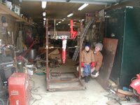
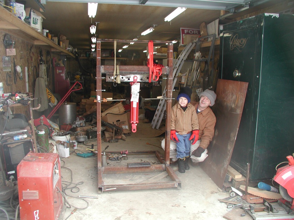
To shorten a long story (that seems to be getting longer as I type this), I pulled together all of my scrap steel and bought some hydraulic cylinders for the "rock-biter" that Mr. G and I were already drawing in the dirt. The hydraulic rams would be powered by tractor hydraulics, and the contraption could attach to the 3pt hitch on the back of tractor - making it mobile. Scoffing at my MIG welder, Mr. G brought over his Lincoln buzz box and got to welding the heavy steel. (That's "rock-biter v1 in progress," Mr. G., Mr. G's buzz box, and one of my sons in the picture.)
Version one worked, but it worked like... uh let me search for the word... ah there it came to me... it worked like
crap. It split rock, but not consistently where we wanted it to split. We split about 50 rocks with it, but our scrap pile was growing faster than our "keep" pile. The splitter even stalled out on a few wimpy 6" thick rocks - clearly we would need that second hydraulic cylinder. Glad the stonemason wasn't around to see Version 1!
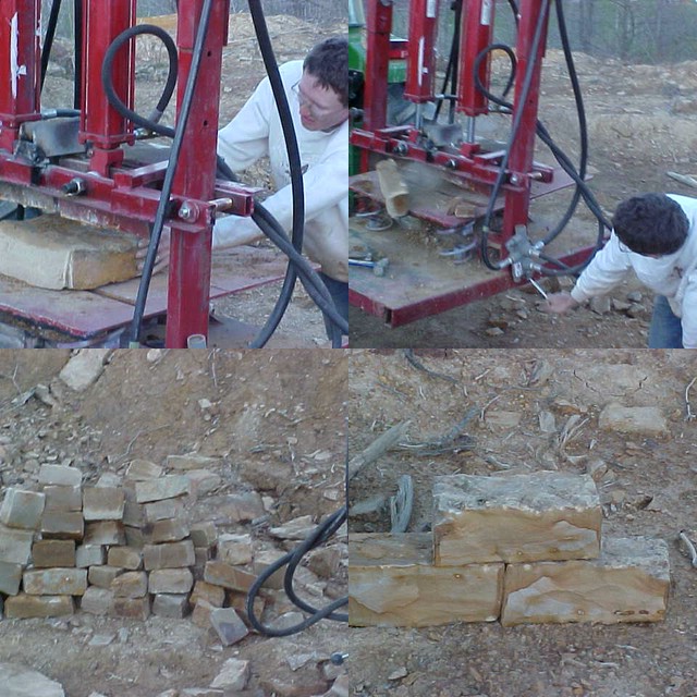
Back to the drawing board... or should I say, back to the (web)crawling board.... We set aside our waning pride and got on-line and looked at some giant commercial versions of stone splitters. We scrutinized, we slowed down the video clips, we studied. Aha, Mr. G. spotted it first. "Go back to that frame... you see that... the bottom table moved a little... it floats on springs and there are wedges on the bottom too - that come up through the table." That _was_ the secret.

Mr. G. went to the local junk yard and found some car springs. (The proprietor wanted $1, Mr. G. offered 50 cents and they begrudgingly settled on 75 cents. This is how business gets done in eastern Kentucky. If you're not from around here and/or unfamiliar with the dance, you'd better just pay the asking price... or you'll leave the junk yard without any springs and no amount of money will buy them.) I got on line and ordered two more log-splitter wedges. Version 2 (shown here), debutted 2 weeks later, and worked like a charm. In less than 8 hours, we split at least as much stone as the stonemason had in about 30 hours. (and we were making good stone out of the ones that he had rejected because they would have been too much work to square up by chisel). Furthermore, the stone split so squarely and so consitently with a clean natural face that we didn't have to "work" the faces with a chisel - quelling my wife's concern that our house would look too formal.
Mr. G. busted version 2 last week on a particularly stubborn rock. In retrospect, the piece that broke was embarrassingly undersized for the job. So, after one more trip to the local metal-yard, we now have the parts to build version 3 (which is basically just version #2 beefed up).

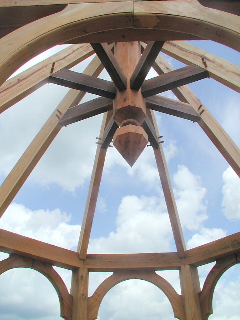
 When I originally designed our timberframe house, I had in mind that we would use SIPs (Structural Insulated Panels) for the walls and roof of our house. The SIPs would have provided adequate stiffening of the roof structure, so wayback, I had omitted any diagonal timber bracing in the roof. But for various reasons, I eventually decided to use the SIPs only for the walls of our timberframe house. Now that SIPs were no longer in the plan for the roof, I needed to stiffen the roof somehow. Some options that I considered were: (1) plywood sheathing, (2) hidden 2x6 braces above the tongue and groove ceilings, and (3) traditional timber braces. Option 1 was undesirable because of the addition of "manufactured" wood that was not from our farm. Option 2 just wasn't honest (hidden braces in a timberframe?!) and would have complicated the insulation. Option 3 would have been an inordinate amount of work, given that the frame was already raised.
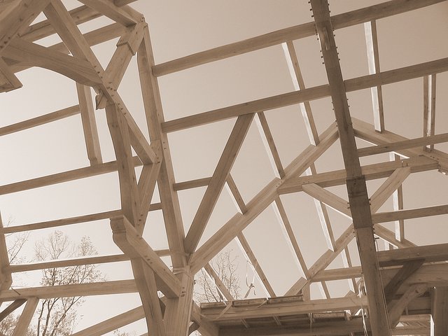
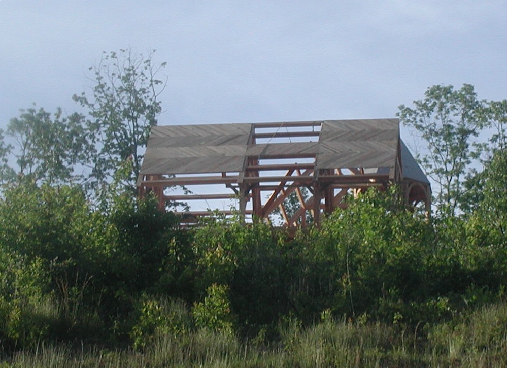 What I came up with was to run our tongue and groove ceiling boards on a 45 degree angle, and switch directions at every purlin. Every tongue and groove ceiling board that we added was therefore going to act as a corner brace in the roof plane. If one brace is good, then hundreds of braces must be even better. But this meant that each end of every board had to be cut on a 45, and all of the boards had to end on purlins. A lot of work... and if we didn't pay attention, a lot of waste when the ends of the boards got trimmed. But as it turned out, because we were careful, none of our waste pieces were ever more than 6" long. In the corner of every purlin-rafter intersection, we got a chance to use up the short boards.
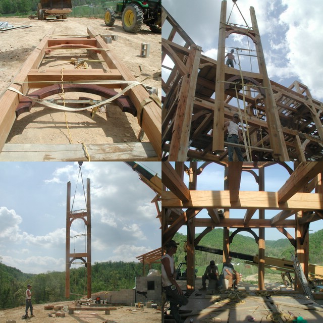
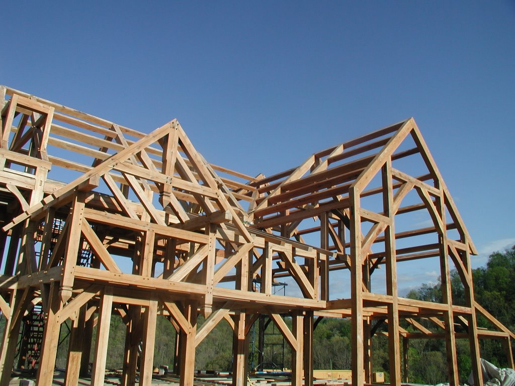
 The weatherman predicted 5 sunny days in a row, which means I had an opportunity to make hay on our farm and get the tongue and groove ceilings down on the biggest plane (the south plane) of our roof and get it covered up. It took 4 of us 3 days to cut and put down about 800 square feet of prefinished tongue and groove and to cover it up with the temporary waterproofing (6mil plastic sheet) that will later act as our vapor barrier. You can see the clear plastic and temporary battens have been applied to the roof in the last picture. This would have been nearly impossible without safety harnesses, good rope, and the crane.